Your project needs a cable, and since USB-C cables are omnipresent now, it’s only natural to want to reuse them for your evil schemes. Ever seen USB 3.0 cables used for PCIe link carrying duty? It’s because USB 3.0 cables are built to a reasonably high standard, both sockets and cables are easy to find, and they’re cheap. Well, USB-C cables beat USB 3.0 cables by all possible metrics.
Let’s go through USB-C cable reuse in great detail, and see just what exactly you get when you buy either a gas station C-C USB 2.0 cable, or, the fanciest all-features-supported 240 W Thunderbolt cable that money can buy. Looking for a cable to cut, or something to pass a seriously high-speed link? You’re reading the right article.
The Omnipresent Cables
USB-A to USB-C cables are the least interesting. They’re equivalent to a microUSB to USB-A cable, except there’s a resistor on the USB-C plug, connected from VBUS to one of the CC pins. That’s it. The cable contains four conductors, there’s really not much new. Save these cables for all the devices still built without the 5.1 kΩ resistors.
Now, a USB-C to USB-C cable – let’s say, 60 W max, the default USB-C cable capability. If your cable says anything less than 60 W, say, “2 A” or “15 W”, that’s a lie – it can handle 60 W no problem, all USB-C to C cables can do 60 W. This cable is also cool – for one, it has five conductors; GND, VBUS, D+, D-, and CC. Two of them (GND and VBUS) are guaranteed to be thick enough to carry 3 A without much voltage drop if any, too!

What does this mean? If you need a five-wire cable to fix your headphones, and you want something solid, a USB-C cable is probably your best bet ever – and you have a ton of choice here. You will inevitably end up with a heap of broken USB-C cables, which means you’ll never be short of 5-conductor cables – the kind of cable that has always been kind of a rarity, unless you’re pilfering headphone cables for your projects.
What about 100 W to 240 W cables? There’s good news and bad news. Good news is, the cable is likely to contain six wires. One extra wire is for VCONN – power for the emarker chip inside the cable plug, a memory chip you can read over the CC line, letting the PSU know whether the cable is indeed capable of carrying over 5 A – required for the 61 W to 240 W range.
Bad news is – there could still be five wires, if the cable is built using the alternative scheme with two emarkers, one per plug. The VCONN wire won’t be present then, and there’s no way to know until you cut the wire apart, so if you’re looking for a six-wire cable, you might have to try a few different cables. Also, the VCONN wire doesn’t connect the two plugs together – it’s isolated at one end, so don’t expect it to help if you use USB-C sockets instead of cutting the cable.
Now, you don’t always want to cut the cable – you can use USB-C sockets and apply your custom five-wire scheme to them. An idea I hear often is using USB-C cables for 3D printer hotends. It makes sense – such cables can handle 60 W of power without breaking a sweat, and you could likely do a fair bit more. Put extruder power onto the VBUS and GND pins, and use the three wires left for a thermistor and a limit switch. But the cable and socket mechanicals might be a dealbreaker. If your extruder-powering cable vibrates out of the socket, you might end up with a high-resistance-contact high-current connection on your hands – a recipe for melted plastic and possibly flames. Try it at your own risk!
You also won’t be able to make such cable reuse standard-compliant, and such port won’t be safe for any USB-C devices someone might plug into it, so label it accordingly, please.
What About Voltages?
What about putting arbitrary voltages onto VBUS, without PD negotiation? Again, it won’t be standards-compliant unless you really put some effort in – mark your jury-rigged sockets and cables accordingly, or they will eat your devices for breakfast. Also, SPR (100 W) cables contain 30 V 10 nF capacitors at each plug end, and EPR cables contain 63 V ones – reach these limits at your own risk, those capacitors are known to fail short-circuit.
Another factor is if you decide to go for the 48 V / 5 A target while bypassing the USB-C standard, because 48 V support is not as simple as putting 48 V on VBUS. If you just put 48 V on the VBUS pins, you’ll really want to figure out spark management, so that suddenly unplugging the cable won’t burn either the plug or the socket or both – PD has ways to deal with that, but they do require you to actually implement PD, specifically, EPR, which brings a heap of safety guarantees due to exceeding the 20 V limit.
That’s about it when it comes to reusing the cheapest kinds of USB-C cables – you get an extra wire compared to previous USB standards, it can handle a fair bit more power, and you can even use USB-C sockets. However, it will kill your devices if you’re not careful, and you need to take extra care if you go over 25 V or so. What about if you want to get more wires and pull some differential pairs instead?
Up The Speed
Fully-featured USB-C cables and sockets are genuinely wonderful for pulling high-speed communications over them. They are built to a solid standard, with proper impedance controls, shielding, and a modern-day understanding of digital transmission standards. Now, what exactly do you get from a fully-featured USB-C cable?

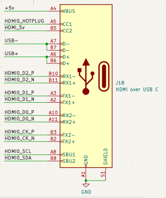
Short answer is, you get six differential pairs, and one single-ended wire (CC), in addition to VBUS and GND. You might want to keep GND at a stable level here, and perhaps don’t mess too much with VBUS. There’s a ton you can do with these six diffpairs – two USB3 ports, or a PCIe x2 link, or two SATA, or HDMI, or CSI/DSI. You can even do Ethernet if you really want to – just don’t expect galvanic isolation to work.
There are nuances, of course! Ever see a teardown or an X-ray of a fancy fully-featured cable? There’s typically all sorts of ICs inside each plug. The first one is the emarker chip, and it’s a fun one to keep in mind. For a start, it will result in some ESD diodes between GND and CC – watch out, don’t bring CC below 0 V or above 5 V.
A second kind of IC is the signal re-driver, used in active cables. You have to provide power to these redrivers through either VBUS or VCONN, just like emarkers. If you don’t do it, your high-speed lines might just be unresponsive to any high-speed signal you apply to the pins.
What about rotation? That’s a tough one – unless your signal is very much like USB3/DisplayPort/Thunderbolt, you might not be able to find a suitable mux chip to rotate your signals. As such, you will likely want to stick to a single rotation and wire your signals directly. Then, if you plug in the cable in an unexpected way, it won’t work, so you should probably consider using the CC pin or the two SBU pins for lighting up LEDs. showing you whether you’re good, or whether you should unplug the cable, rotate it, and plug it back in, like in the good old days.
There’s one last thing you might care about. USB-C cables connect TX on one end to RX on another end, and vice-versa. This is nice for PCIe purposes, since it, too, flips pair naming at the connector. For any other signal, you’ll want to keep it in mind – RX1 won’t go to RX1 on the other end, it will go to TX1, and you’ll have to re-layout accordingly. Unfortunately, I’m not intimately familar with active cable inner workings – so, it’s hard for me to tell whether any active cable redriver chips would reject certain sorts of signaling, perhaps, signals that don’t match USB3, DisplayPort or Thunderbolt signaling types.
And One Last Hack
These are the basics of what you should know before you try and reuse a USB-C cable, no matter its complexity. That said, here’s an extra hack before we conclude!
Only one USB2 pair is actually connected at the USB-C cable end – the pair on the same side as the CC pin. My guess is, this was initially done to avoid stubs and cable plug PCB routing complications, as well as to accomodate standards like VirtualLink. Regretfully, we never got VirtualLink cables, which would allow us to use seven differential pairs at a time, but there is another hack we still get out of this!
What does this mean for you? If you use two USB2-grade 2:1 muxes, you can get two extra differential signals out of a fully-compliant USB socket, and they won’t even interfere with standard-compliant cables. Use this for SWD, JTAG, or whatever else, with your signals broken out through a custom plug – just make sure you dutifully switch the muxes depending on cable orientation, then you can keep your USB2 cake and eat it, too.